Schematic of the AC50 mark 1 - OS/044
Early 1964, single channel, valve rectified, two input and four input models
Around 400 amps were built to this circuit, January to July 1964.

First circuit drawing of the AC50 Mark 1 circuit - OS/044. Click to enlarge (and to download the full-sized image). A number of amps had a slightly modified bias circuit, as noted below.
Below, thanks to Martin Kelly, a copy of Rodney Angell's circuit diagram for the AC50 Mark 1 - a larger version to follow. Before moving to the organ department, Rodney was an amp tester and service engineer at JMI. Note that the numbering of components has been started in pencil in the upper half of the sheet. Size is old-fashioned foolscap (13" x 8").

Rodney Angell's copy of OS/044.
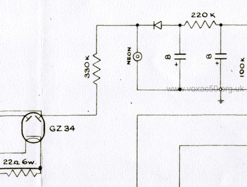
OS/044 unfortunately slightly mis-represents the arrangement of the 22R resistor in relation to the rectifier valve. Below a detail of OS/053 to show its true relationship.

Detail of OS/053 to show the true relationship of the 22R resistor in relation to the GZ34.
A note on the bias circuit


Click for larger images
Above, parts of the two earliest AC50 schematics that survive - OS/044 for the single channel amps (two-input and diamond-input); and OS/053 for the twin channel amps (see below for a full version, redrawn).
Very few, if any AC50s seem to have been built exactly to OS/044. Generally there is a second 220K resistor parallelled across the 220K specified in the schematic, bringing the total resistance at that point to 110K - pretty much in line with OS/053.

The second 220K resistor is piggy-backed across the larger white one at the top of the board
Second, as has been kindly pointed out to me, there is sometimes a third 220K underneath, and in parallel with, the 25K trim pot, limiting the effective value of the pot to 22.5K.

The purpose of these changes was evidently to increase the scope for bias adjustment in the two-input and diamond-input amps - most likely an initiative undertaken at Triumph.
The bias voltages indicated in OS/044, -32 to -35v, will therefore have been brought closer to the values later expressed in OS/053, -32v to -40v. Presumably the range -32v to -35v was felt to be too limiting, running less strong EL34s too hard.
The little neon lamp was a current and voltage regulating device, acting much as the larger lamp limiters (placed in series with mains positive line) that old radio men used to use for testing potentially defective devices.
Circuit diagram of the AC50 mark 2 - OS/053, first version (undated, unreleased)
Two channel, valve rectified, four inputs (small and large boxes)
A detail from a copy of the diagram, latterly owned by Rodney Angell (see above). This first version of OS/053 is much the same overall as the approved "release" version below, but its bias circuit follows OS/044 - note the 220K resistor "across" the 8uf capacitors. OS/053 second version has 100K.
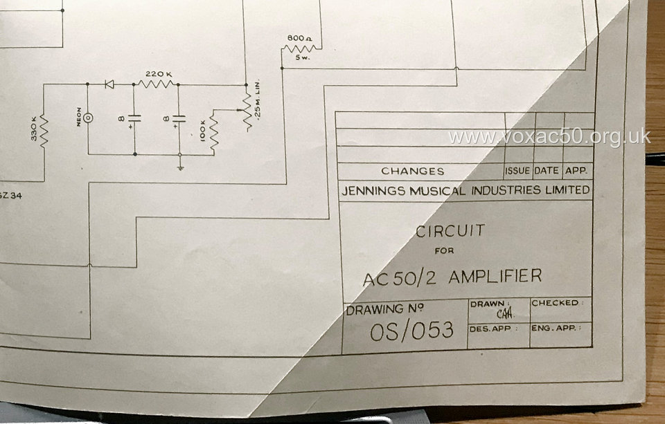
AC50 mark 2 - OS/053 - first version. Information panel - no dates or changes.
AC50 mark 2 - first version.
Circuit diagram of the AC50 mark 2 - OS/053, second version (released)
Two channel, valve rectified, four inputs (small and large boxes)
Around 800-900 amps were built to this circuit, last third of 1964 to early 1965
Good original copies of this diagram are hard to come by. There are a couple of "restored" versions in circulation, but these are not without their drawbacks.
Below, a copy that came in with a batch of material held at one time by "Modern Music" in Dudley. Serial number 1622 may have been repaired from it. Component values that are indistinct or very small in the original have been supplied in blue type. Note the dates in the info panel - first recension 17th April 1964, second 16th July 1964 - which pretty well corresponds with the release of the new Mark 2s. The second recension is given as 16th March 1964 in at least one recent digitally "corrected" version, but that makes little sense given the first date. It could be that the line "Voltages and Valve Numbers added" was simply put in the wrong box.
A version of OS/044 - the circuit of the AC50 Mark 1 - has come to light with JMI additions bringing the circuit into line with the Mark 2. A copy will be provided soom.

A detail of the info panel of OS/053.

Right hand side of OS/053. Click on the image for a large downloadable version (2400 pixels tall)

Left hand side of OS/053. Click on the image for a large downloadable version (2400 pixels tall)
Schematic of the wiring of the XLR speaker connectors - OS/054
Drawn up for new large box AC50s

The sheet is undated, though was clearly drawn up shortly after OS/053 for the large box AC50 mark 2. Note that small box AC50 mark 1s do not have an impedance selector on their back panel.
Schematic of the AC50 mark 3 - OS/072
1965-1967, two channel, solid state rectified, four inputs
Around 4000 amps were built to this circuit.

Schematic drawn on 7th January 1965. 14th October 1965 addition of the brimistor noted.
Schematic for the Vox add on reverb unit - OS/075

Schematic drawn on 15th Jan. 1965 primarily for Vox AC30s, but the unit was certainly fitted to a small number of AC50s too.
Schematic of the AC50 mark 4 - OS/163
1967-1968, two channel, solid state rectified, four inputs
Around 700 JMI amps were built to this circuit.

Schematic drawn on 10th April 1967. Adjustments noted July, September 1967, and October 1969 ("Vox Sound Equipment Limited").
Parts list for the solid state rectified AC50 issued by Thomas Organ in 1967
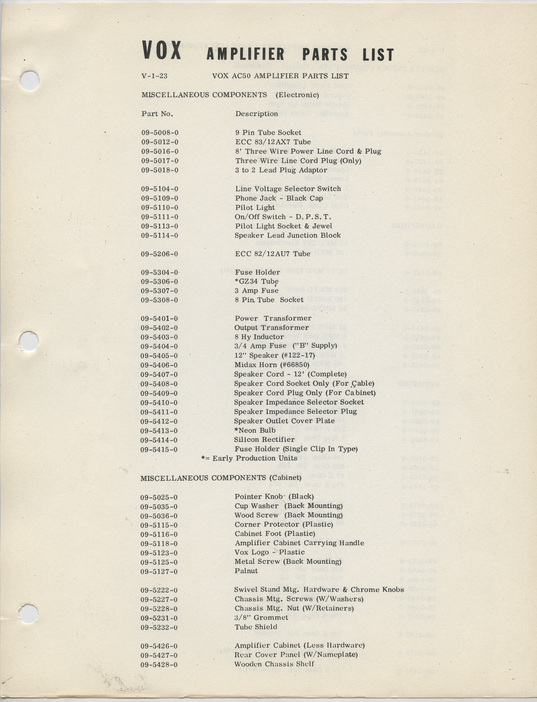
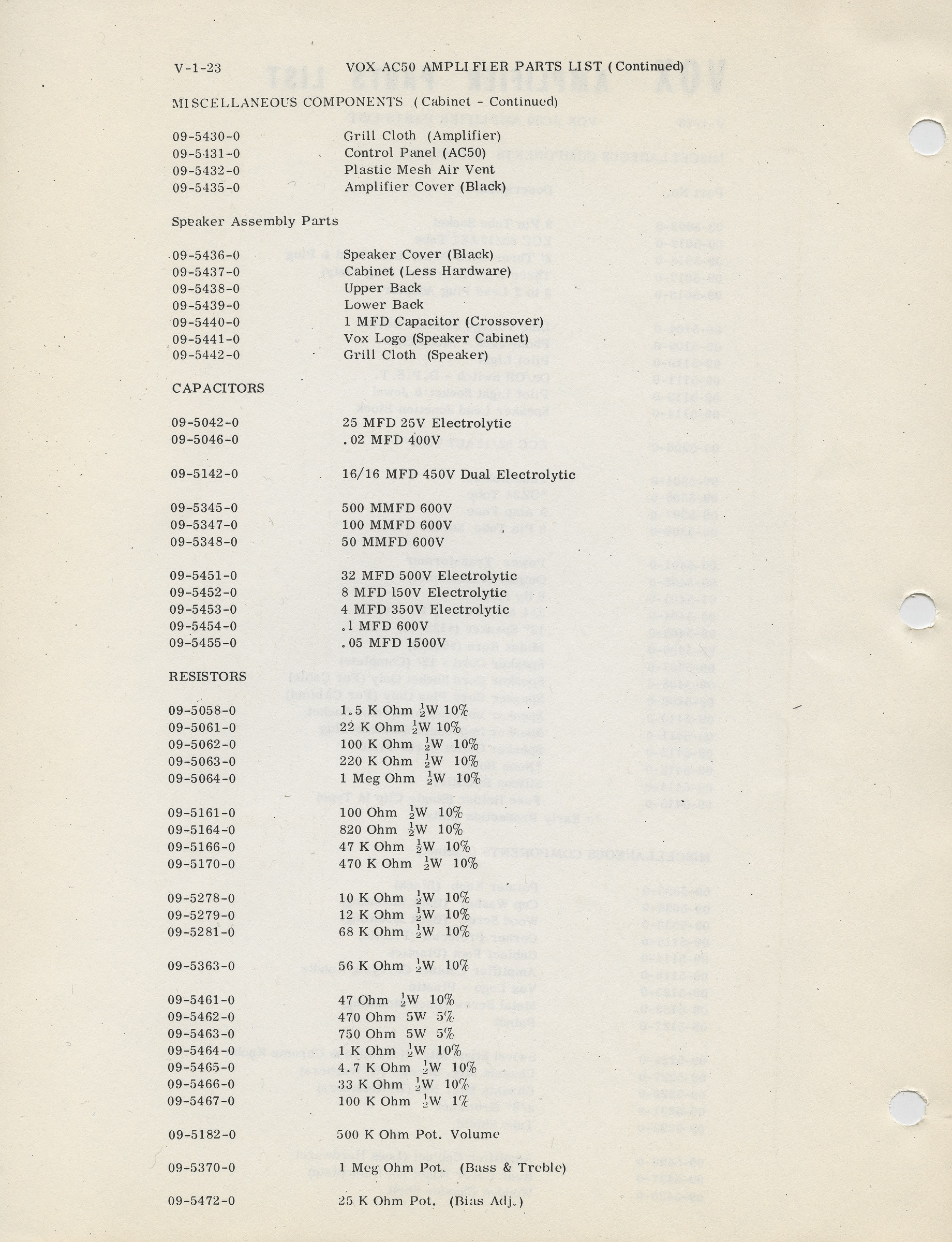
Older versions of this list probably survive in older versions of the service manual, though the roster of items should hardly differ. Note that provision is made for the servicing of valve rectified amps too: the GZ34 and the neon bulb (employed in the bias circuit).
Parts Price List for AC50s issued by Thomas Organ in April 1969


