The design of the AC50
Derek Underdown (power section), Dick Denney (preamp tone circuit)
The purpose of this section is to bring together documented notes on the design of the Vox AC50 - the AC50 mark 1 (single channel, copper control panel, two inputs first, then four in a diamond configuration).
Design began in the summer of 1963, running in parallel with the design of the cathode biased AC80/100.
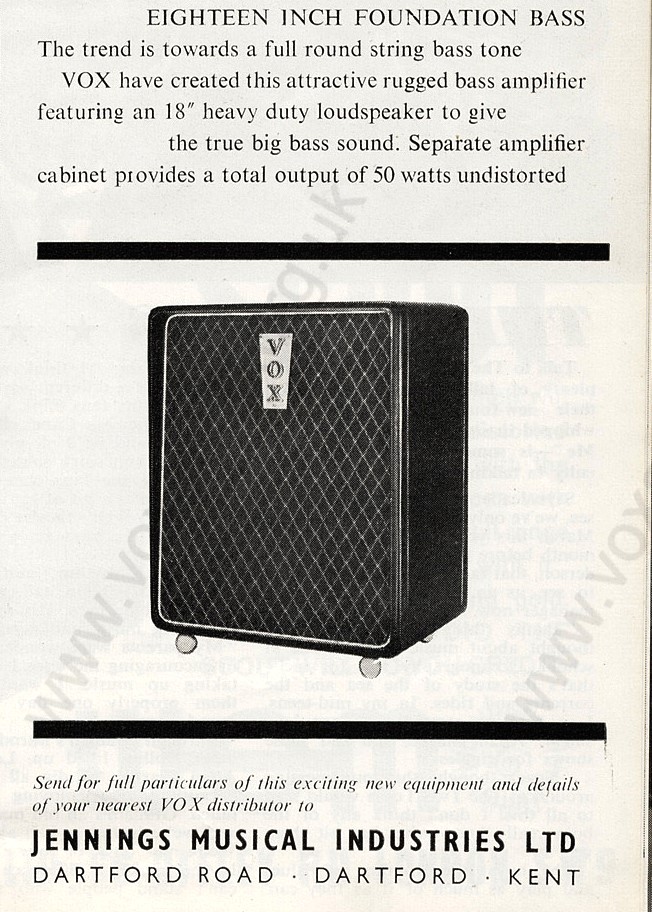
"Beat Instrumental" magazine, August 1963, signalling the arrival of Foundation Bass speaker cabinet along with the new amplifier. But it was some months before the AC50 made it to market. "50 watts undistorted" (from two EL34s) was somewhat hopeful, but good marketing twaddle nonetheless.
There have long been whispers that the AC50 was intended initially to be cathode biased too. But this is fanciful. A cathode biased AC50 would only produce around 34 watts at most (as tested in practice). The purpose of the AC50 was to produce substantially more power than the AC30 - so fixed bias was the topology chosen, not least because the circuit had already been worked out at JMI back in the 1950s (see below). As for a preamp, that already existed too in the shape of the Top Boost circuit designed by Dick Denney in 1961 for the AC30.
All in all therefore, the electronic design of the AC50 was not difficult. Perhaps the trickiest thing was the practical or "mechanical" side of the process - the layout of the chassis, tagboards, and main components. The approved prototype was sent to Triumph Electronics (one of JMI's contractors) in late 1963 to serve as a model for production. Graham Huggett, the "chassis beater" at Triumph, remembers the model that arrived from JMI well. Once it had served its purpose - all elements inspected and documented for production on the work-benches - Graham acquired the amp and used it on stage with his band.
POWER SECTION
The power section, with its fixed bias circuit, was the work of Derek Underdown. The story begins with the "30W Amplifier" circuit designed by Derek for JMI organs in the mid 1950s. The schematic survives.

A detail of the circuit diagram for the mid 1950s JMI "30W Amplifier" showing the bias section. Thanks to Glen Lambert for the copy.
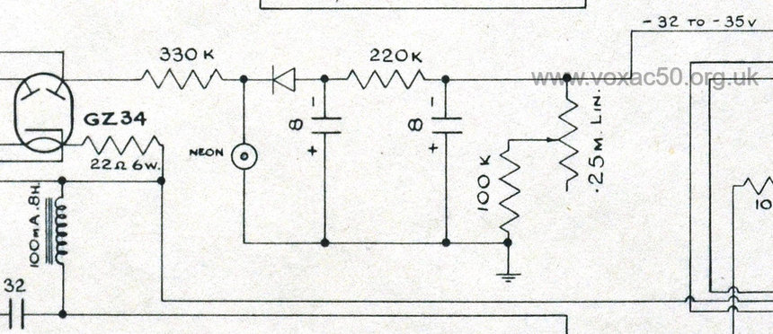
A detail from OS/044.
Note the almost identical arrangement: 330k resistor, neon light bulb (to limit the current and to a certain extent the voltage), the 220k resistor, two 8MFD capacitors, and the 250k trimpot in series with a 100k resistor. This is all Derek's work. And it was Derek who had experience of working with EL34s in fixed bias. The JMI AC2/30 of late 1957, a 30 watt all-purpose amplifier, was based on the "30W Amplifier" too - see this page on the Vox AC30 website.
Below, images of the circuit of a surviving 30W Jennings organ amplifier (thanks to Glen Lambert for the identification); and the bias circuit of an early AC50 Mark 1 (thin edged box).

Note at right on the tagboard the neon bulb and the diode bolted to the chassis to its right.

The underchassis bias board of an early AC50 mark 1.
At least one former Vox employee (besides Derek and Dick) has indicated that he was involved in the "design" of the AC50 - presumably at the level of assembly or testing. But Derek and Dick were the main players, the others their assistants.
Around one hundred AC50s were initially made by Triumph (single channel, two inputs), copied from the model sent from Dartford Road in late 1963. Surviving examples can be seen on this page. The design was re-jigged a couple of months later to include four inputs in a diamond formation. The wooden cabinet changed at this time too - thicker edges and a different type of back panel.
Graham, who made the chassis at Triumph, recalled that AC50s never made 50 watts when tested, 46 watts at best.
An ancillary note on the AC50 bias circuit.
As has already been indicated, Derek simply re-purposed the system he had adopted in the 1950s for the Jennings Organ Company's 30- and 50-Watt amplifiers. A key part of the circuit is the neon indicator lamp, used to help stabilise the voltage. In the 1950s, the lamp was known as a "CC3L". In the 1960s, the designation was "NT2", though the specifications remained the same. Some units were also marked CV2266, a military number, "CV" standing for "Common Valve". An alternative was the CV2213.

The neon lamp in an two-input AC50 mark 1 (serial number 1034).

Detail of the circuit diagram for the Jennings Organ Company 30-Watt amplifier.

Detail of the circuit diagram for the Jennings Organ Company 50-Watt amplifier.
The operating parameters of the neon lamp are given as (pdf of the specifications of 1955):
Max. striking voltage - 85v
Max. anode current - 0.65mA
Min. anode current - 0.05mA
Regulation change in voltage for a change in cathode current from 0.5-0.3mA - 3v
An earlier form of voltage stabiliser - the Mullard 7475 - was used by Derek for the Jennings organ power pack sections.
PREAMP
As has long been known, the preamp tone circuit of the AC50 is effectively based on the Top Boost circuit designed by Dick Denney for the AC30 in the second half of 1961; the first gain stage (the first valve after the input jacks) and the phase inverter stage (the last preamp valve) had already been worked out in the normal channel of the AC30/6:

JMI circuit diagram sheet OS/010. The add-on Top Boost circuit designed by Dick Denney for the AC30, principally in late 1961 the AC30 Super Twin (separate amplifier section and closed back speaker cabinet).

A detail from JMI OS/044, autumn 1963, for the AC50 Mark 1.
The details above show the circuitry around the second valve in the AC50 preamp (V2) - an ECC83. One finds the same tone circuit in the AC80/100.

Detail of the preamp of AC40 mark 1 serial number 1034.
The valve in the first gain stage (directly after the input jacks) is an ECC82 (V1), as it also is in the AC80/100. The only difference between the circuits of in the AC50 and AC80/100 at this point is the value of the capacitor that couples this first stage to that of the tone circuit - 0.047uf in the AC80/100, and 0.022uf in the AC50. The 0.022uf lets more treble through. 0.047uf is the value used in the Normal channel of the AC30/6.
The circuitry around the third and last preamp valve in the AC50 (V3) - the "driver" or "phase inverter" - is much the same as that of the AC30/6. V3 in the AC80/100 is balanced differently due to differences in voltage and load.
The preamp of the AC50 was therefore created by Dick Denney from pre-existing JMI designs much as Derek had done for the power section.