The design of the AC50 mark 2
Derek Underdown (power section), Dick Denney (preamp tone circuit)
The purpose of this page is to bring together documented notes on the design of the Vox AC50 mark 2 (two channel, valve rectified, grey control panel), produced from the autumn of 1964 through to early 1965. A page on the design of the AC50 mark 1 can be found here.
Design of the Mark 2 began in the early summer of 1964, the intention being (i) to increase the tonal range of the amplifier, and (2) to update its format (and that of the accompanying speaker cabinet). So far as one can tell, production was set in motion in early August 1964, the new large-box version of the amplifier shown for the first time at the Russell Hotel Trade Fair in late August 1964. A photograph taken in the Dartford Road works before 4th September '64 shows large-box AC50 Foundation Bass sets being packed for America. Production, promotion, and sales took place at pace.
POWER SECTION.
As in the case of the preamp, the power section of the AC50 mark 2 is based closely on that of AC50 mark 1.
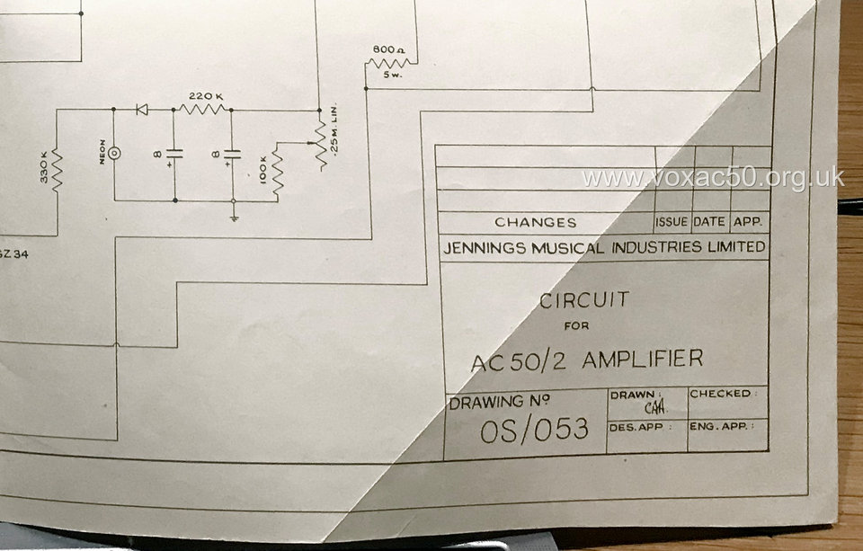
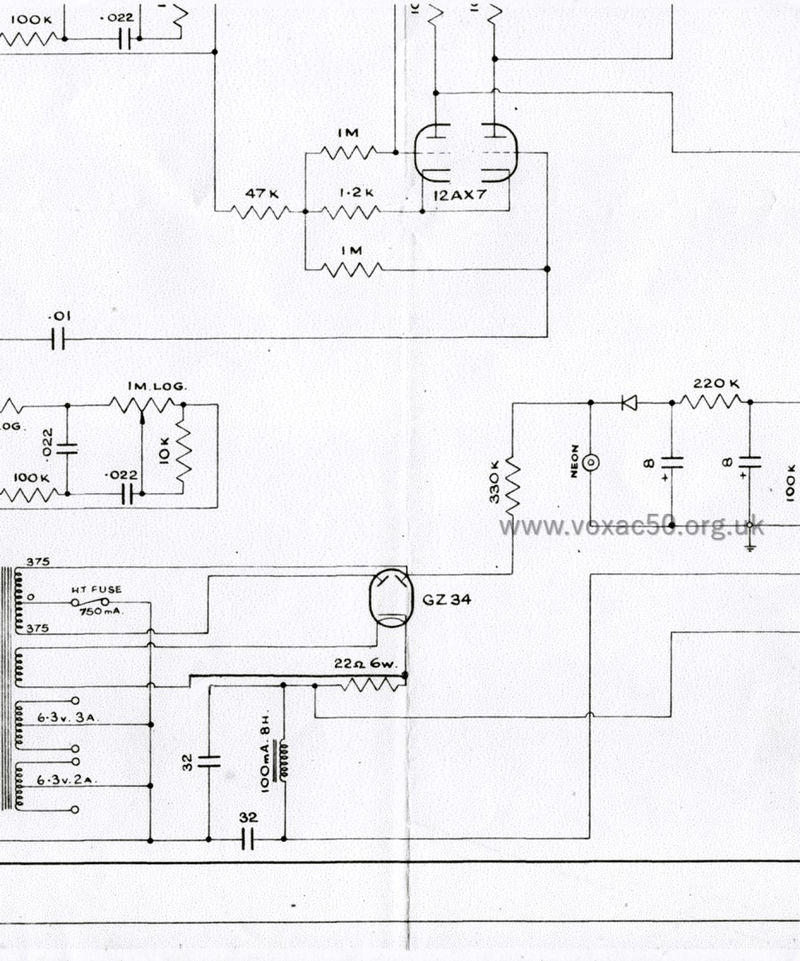
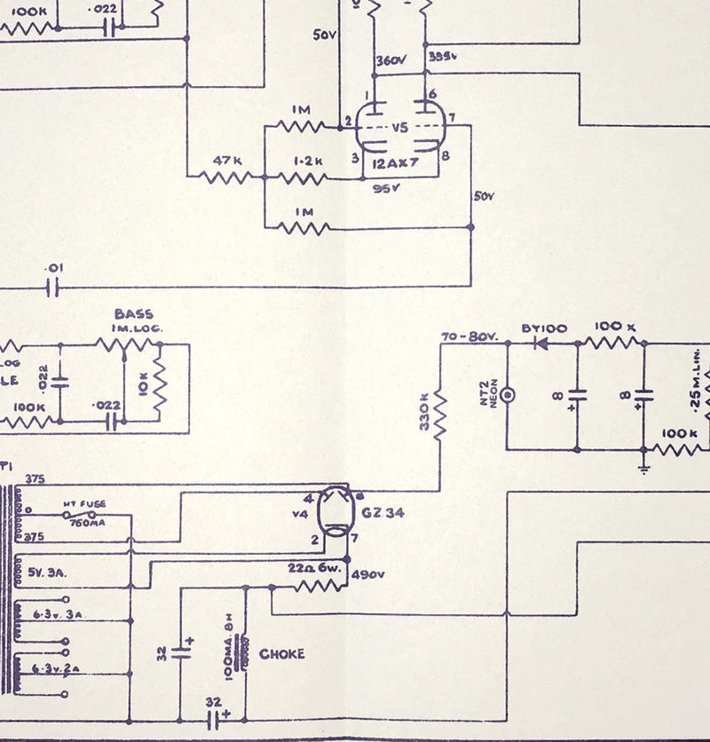
A JMI circuit diagram for the mark 2 that has recently come to light - a preliminary version of OS/053 - throws some interesting light on at least one important aspect of the design process: how the bias circuit of the new amplifier was arrived at. The sheet belonged to the late Rodney Angell, who worked for JMI for eight years, first as an amp tester, then as a Research and Design Engineer.
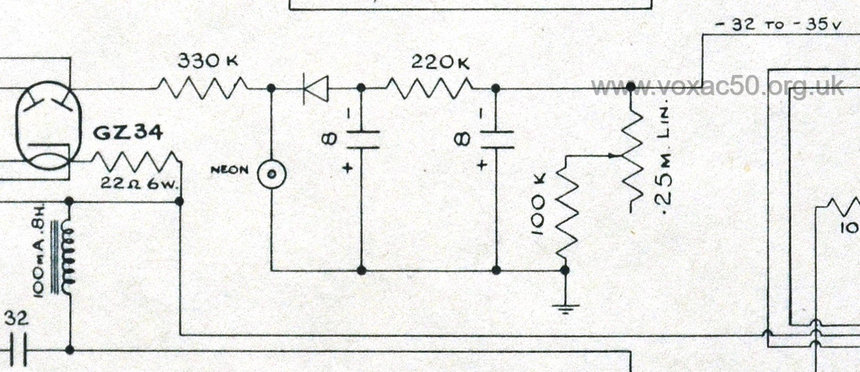
AC50 mark 1 - OS/044
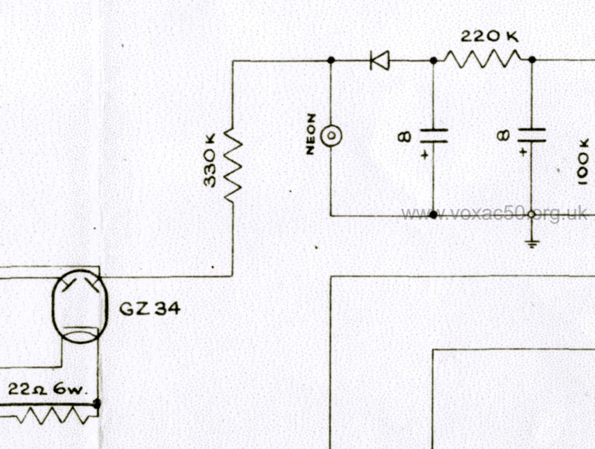
AC50 mark 2 - preliminary version of OS/053. Printed for works use only.
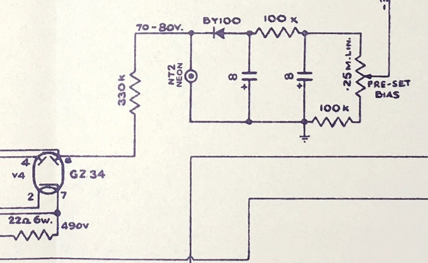
AC50 mark 2 - standard (published) version of OS/053.
The preliminary version of OS/053 diverges from the standard sheet in other ways too - valve pin numbers, voltages, certain component names, and so on, are absent. Below, a detail of its information panel. Note that there no dates or numbers are provided.
AC50 mark 2 - OS/053 - preliminary version. The bias circuit is still that of OS/044. Thanks to Martin for the pic. from which this detail is taken.
The sheet is otherwise much as the standard version of OS/053 but with the bias circuit of OS/044, and without the notes on voltages, component types, valve pin numbers, and the 470R resistor on the 15ohm terminal of the output transformer. Below, a larger detail and the corresponding section in OS/053 as published:
Rodney Angell's sheet for the AC50 mark 2.
Standard OS/053.
It is well to remember however that what we are seeing are "snapshots". The circuit diagrams issued by JMI are in large part not design blue-prints - they were for the benefit of repairmen. JMI's contractors - Westrex, Triumph and Burndept - had their own working circuit and "build" diagrams.
An ancillary note on the AC50 bias circuit (also relevant to the AC50 mark 1).
As has already been indicated, Derek Underdown simply re-purposed the system he had adopted in the 1950s for the Jennings Organ Company's 30- and 50-Watt amplifiers. A key part of the circuit is the neon indicator lamp, used to help stabilise the voltage. In the 1950s, the lamp was known as a "CC3L". In the 1960s, the designation was "NT2", though the specifications remained the same. Some units were also marked CV2266, a military number, "CV" standing for "Common Valve". An alternative was the CV2213.

The neon lamp in an two-input AC50 mark 1 (serial number 1034).

Detail of the circuit diagram for the Jennings Organ Company 30-Watt amplifier.

Detail of the circuit diagram for the Jennings Organ Company 50-Watt amplifier.
The operating parameters of the neon lamp are given as (pdf of the specifications of 1955):
Max. striking voltage - 85v
Max. anode current - 0.65mA
Min. anode current - 0.05mA
Regulation change in voltage for a change in cathode current from 0.5-0.3mA - 3v
An earlier form of voltage stabiliser - the Mullard 7475 - was used by Derek for the Jennings organ power pack sections.
PREAMP
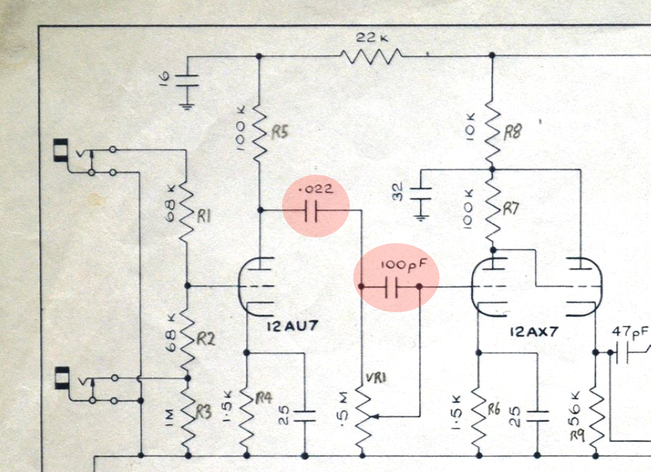
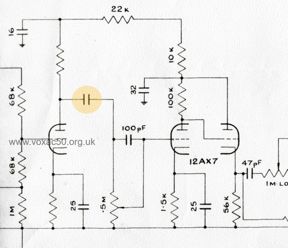
Tthe preamp of the AC50 mark 2 did not take long to design either. A second channel - the Brilliant Channel - was added, mirroring the general form of the Normal Channel but with capacitors designed to block bass and accentuate the treble response - 500pf and 100pf. The capacitors in view and their analogues are highlighted on the sheets. 500pf, it should be said, had been used in the Briiliant Channel of the AC30.
AC50 mark 1, detail of OS/044.
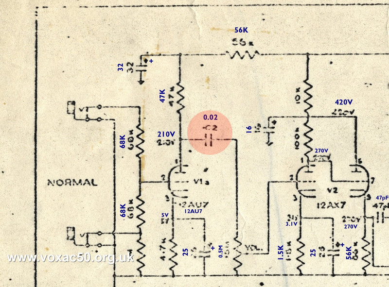
AC50 mark 2, Normal channel, published version of OS/053. Coupling cap: 0.02uf. The removal of the 100pf cap of OS/044 was a move to increase bass response.
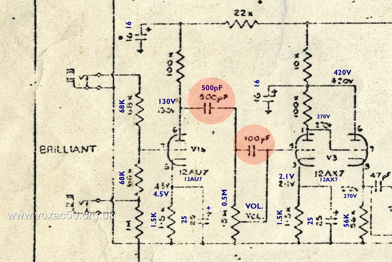
AC50 mark 2, Brilliant channel, published version of OS/053. 500pf is 0.0005uf, in other words 40x less than 0.02uf.
But there was evidently some pause for experimentation in the design process. In the preliminary version of OS/053 values for the two key capacitors in the Normal and Brilliant Channels are not given - presumably not having been decided upon. All other values are given throughout the sheet.
AC50 mark 2, Brilliant channel, preliminary version of OS/053.